


This John Stears manual provides a thorough overview of the remote operation of the Star Wars R2-D2 robot. From its decorative exterior lighting to the internal mechanisms that drive its movements, the manual provides a comprehensive guide for enthusiasts, engineers, and anyone eager to delve into the technical details of the orginal R2-D2.
While the descriptions in the manual may lack systematic categorization, each element discussed can be appropriately classified under one of the six subsystems:
Subsystem: Traction Drive
The robot's traction drive features three forward speeds but lacks reverse capability. These three forward speeds are achieved by varying the voltage to the subsystem at 12 volts, 24 volts, or 36 volts
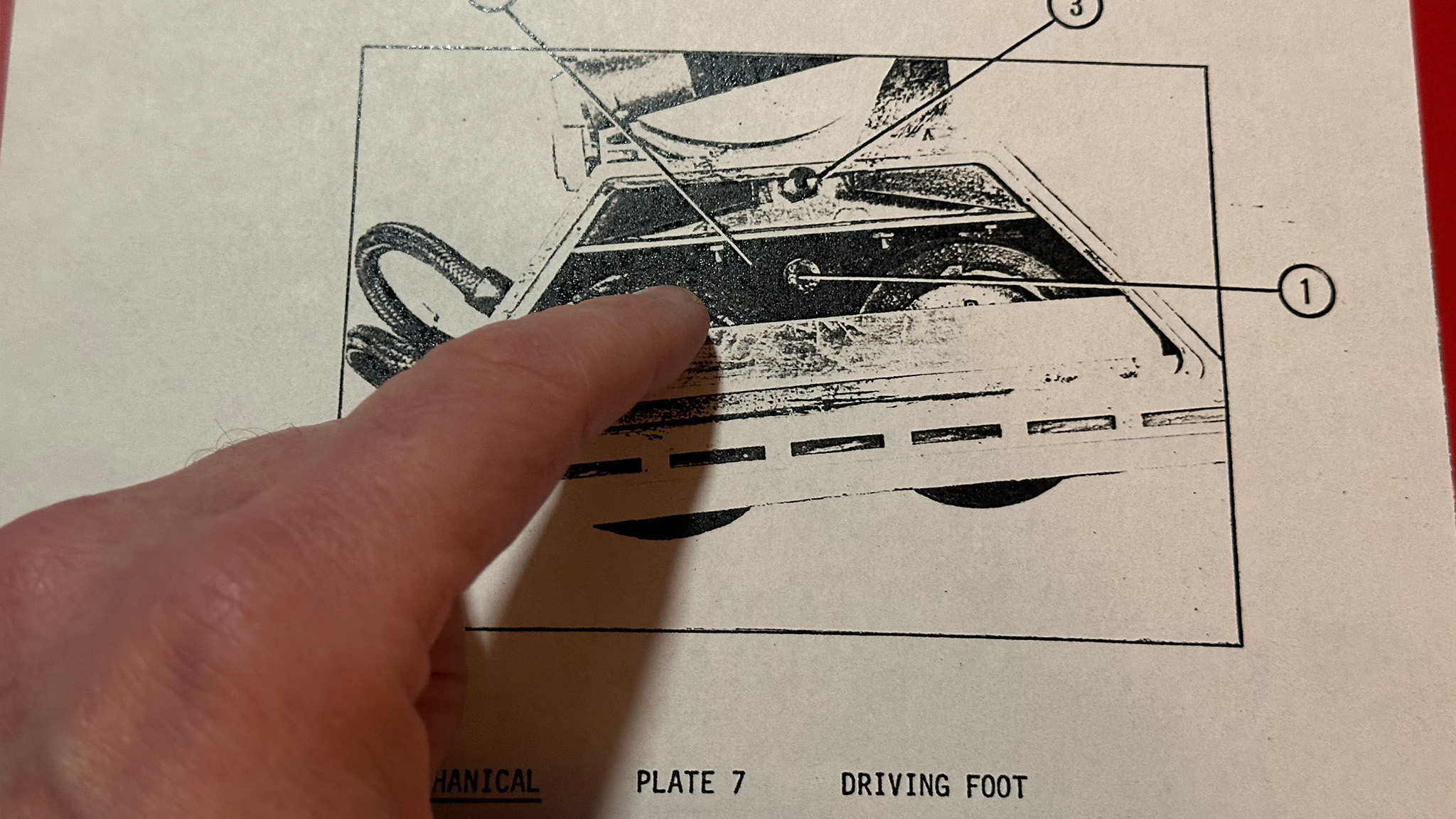
To achieve forward motion, the two feet attached to the standing legs are equipped with individual geared traction motors that drive the twin in-line wheels via chains and sprockets.
Both rear feet incorporate driving motors that propel the wheels through gearboxes, chains, and sprockets.
While the gearboxes are fully enclosed, the chains and sprockets inside the feet are prone to clogging with debris pushed up by the wheels. Regular cleaning and oiling are recommended.
Forward motion directly following a leg drop, utilizes a wire to maintain each leg at the correct distance from the body. However, it fails to sustain this distance during turns, as the inside leg tends to move forward, disrupting the overall balance. When the robot needs to run in its three-legged form, distance struts should be fitted.
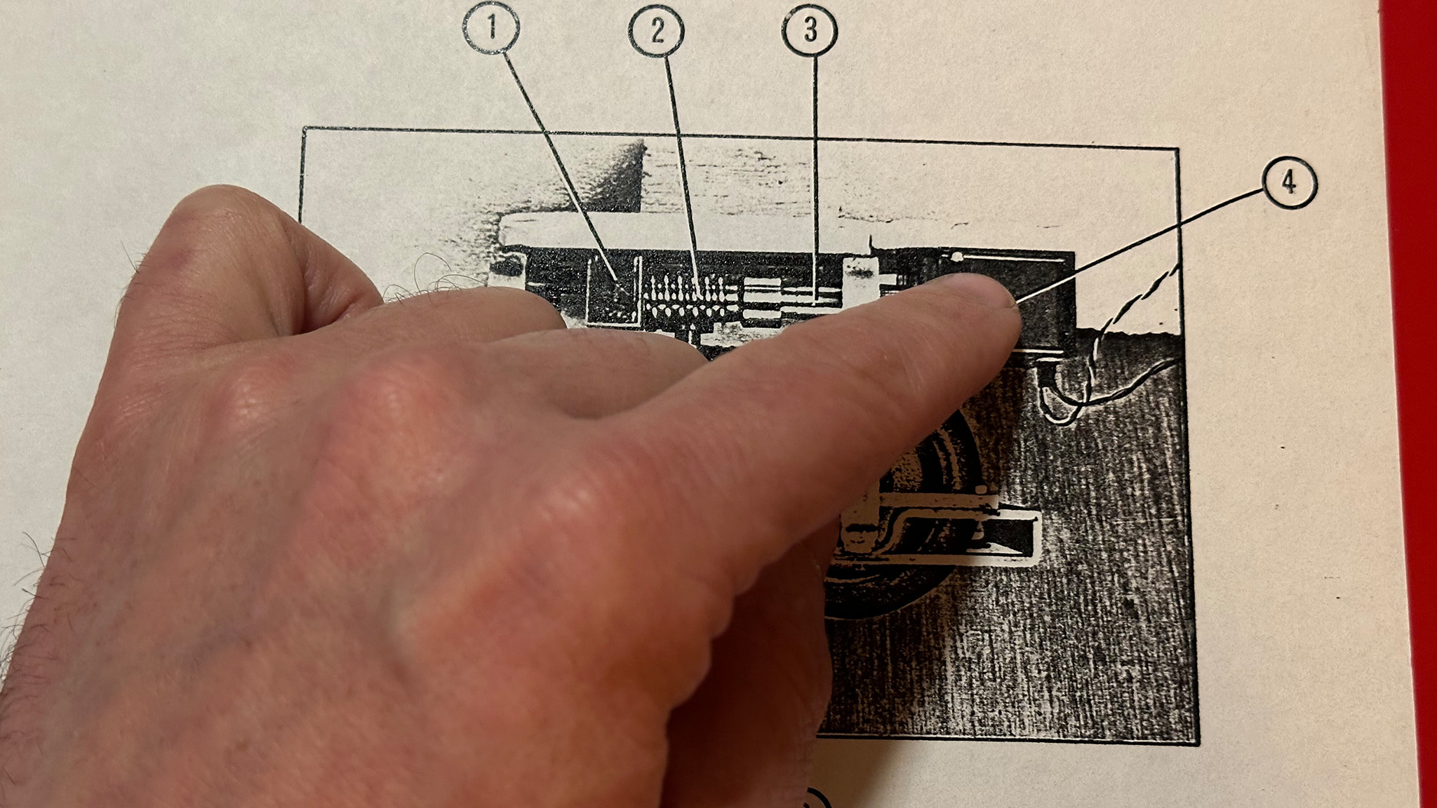
Although not explicitly specified by the manufacturer or part number, photographic plates reveal that the geared traction motors are Lucas 17W windscreen motors. Each Lucas 17W connects to a 23-tooth sprocket, which drives a 1/4" motorcycle chain with 20 links. The chain, in turn, drives two wheel sprockets, each fitted to a wheel
Subsystem: Leg Drop
The robot is designed with provisions for transitioning between the two-legged and three-legged configurations.
When the center foot and ankle retract inside the body, they are secured in the upper position by safety latches.
Conversely, when the center foot and ankle are extended, they are held in position by safety latches in the lower position
In the two-legged configuration, it is essential that the robot be balanced or supported. Similarly, in the three-legged configuration, the leg ties must be in position for stable performance, especially when executing tight turns.
It remains crucial in the two-legged configuration that the robot be balanced or supported
To raise and lock the leg in its upper position inside the body, follow these steps:
- Remove the head to gain access to the drop mechanism.
- Push the body back and tilt it so that the legs and body are vertical and in line. At this point, the locking rod should latch with the locking arm.
- While holding the body in a vertical position, release the lower leg lock (down position) and push the leg upwards until the top leg lock engages.
- Replace the head.
- Hold, support, or balance the robot in a vertical position. (Note: If the body is allowed to drift out of line with respect to the legs, the leg drop mechanism will trigger, and the third leg will drop).
Subsystem:Steering
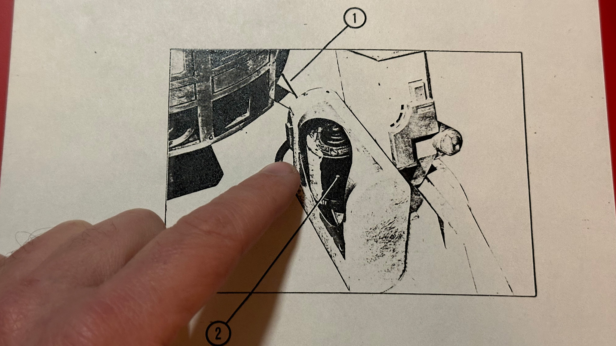
The robot is steerable, and steering is achieved through a mechanism installed in the third (front) foot.
This mechanism is powered by a servo unit, offering proportional and self-centering capabilities.
The foot features twin in-line wheels that should remain parallel to one another from one lock to the other.
The steering mechanism features both wheels mounted on a swivel frame, ensuring that the wheels remain parallel when turning from one lock to the other. The frame is rotated by the servo through a worm and wheel mechanism. -->
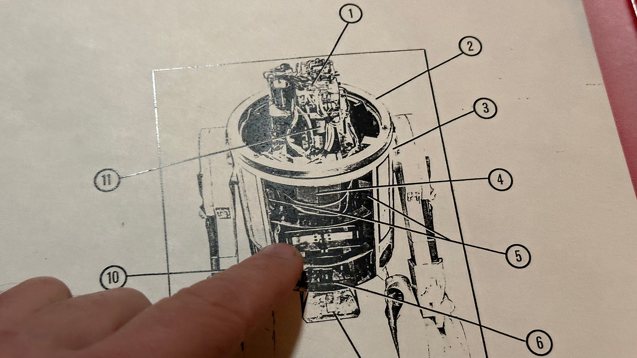
Subsystem:Head Lighting
The robot is equipped with three blocks of simulated computer lights in the head, accompanied by two pulsating lights. The head design closely matches the version used in Kenny's R.2 in all crucial details.
The pulsating light 'throb' drives are housed in two boxes fixed underneath the radio control platform. The circuits drive the bulbs in series, so the failure of one bulb will mean that the other will not light. Incorrect polarity can damage the units, and a discharged battery may adversely affect the 'throb.' The 'throb' lights are fitted with colored gels that may need replacing. The bulbs should seldom need replacing as they are under-run.
The fiber optic displays are lit by means of a halogen lamp (50W) that passes through the colored disk and is focused on the ends of the fiber optic bundles. The disk is turned via a belt drive by a small 6V geared motor unit
Subsystem:Power
The robot contains four DC electrical systems running at 36V, 12V, 6V, and 4.8V.
| Circut | 36V | 24V | 12V | 6V | 4.8V | ||
| Traction motors | x | x | x | ||||
| Leg drop soleniod | x | ||||||
| Fiber Optic halogen lamps | x | ||||||
| Pulsating 'throb' light drives | x | ||||||
| Pulsating 'throb' lamps | x | ||||||
| Fiber Optic light drive motors | x | ||||||
| Steering servo | x | ||||||
| RC reciver | x | ||||||
| Speed control servos | ? |
Speed control is achieved through a servo/micro switch mechanism and associated relays, providing 12-24-36V drive to the two traction motors.
The radio circuits are supplied by a DEAC switched by a slide switch in a recessed panel on the lower left-hand side of the body. The 6V and 12V circuits driving the head display lamps and motors are switched by a large toggle at the lower center of the body at the back.
The two 6V cells comprising the 12V circuit are removable for charging purposes, while the six traction batteries are not removable and must be charged in situ.
All cabling to batteries is done with twin cable, with the conductors connected in parallel. Connectors are of the 'push-on' automobile type, except for the radio control system, which uses its own three-pin plugs and sockets
Subsystem:Remote Control
This version of the R.2. Unit is radio controlled and is intended as a three legged rolling verions of "Kenny's R.2.
Speed is controlled by the left-hand stick, ranging from zero when pulled right back towards the operator to maximum when fully forward. Adjusting the trim control may be necessary for the full range (Stop - Slow - Medium - Fast). Speed control utilizes a servo/microswitch mechanism and associated relays, providing 12-24-36V drive to the two traction motors.
Steering is controlled by the right-hand stick which is fitted with a simple mechanical adaptor that reverses the stick movement so as to provide true directional steering. (The steering servo and mechanics produce 'reversed' steering.) When it is necessary to replace the microswitches, care should be taken to ensure that the arm profiless are carefully copied. Where posible use the original arms.
The front leg "drop" is triggered by the auxiliary toggle switch.
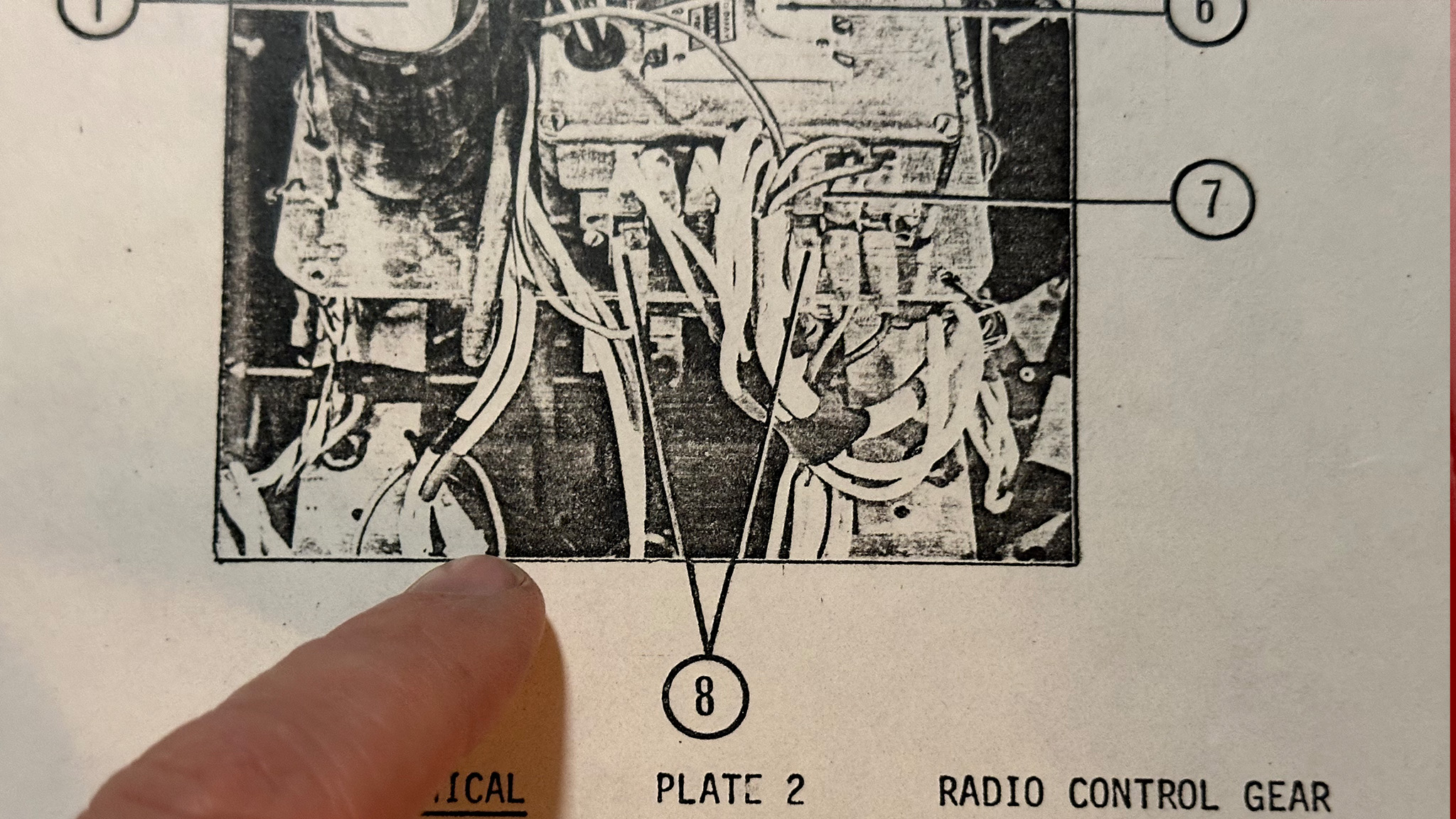
The receiver is powered by a battery, easily inserted into its housing using a push-fit mechanism. The receiver is securely mounted to facilitate access to xtal and servo sockets; it is recommended not to relocate it. The receiver's aerial has been intentionally shortened. For optimal performance, extend the aerial to the outside of the head using fine enameled wire, ensuring it is kept as far away from the body as possible. Whether hanging or trailing, the effective length of the aerial is determined by the portion outside the head. --